
How Custom Precast Concrete Mold Tooling Gets Specified and Built
Yes, custom precast concrete molds can be built from your own drawings. Here is exactly what a mold manufacturer needs from you before it can quote.
Yes, custom precast concrete mould tooling is routinely built from a producer's own drawings, and the process starts the moment those drawings reach the mold builder. From there it is an engineering conversation: the builder reviews the part geometry, advises on mold configuration, and asks how you will place concrete, what cycle time you are targeting, and how many parts you expect to cast. Those answers change the tooling as much as the part outline does.
Most delays in custom tooling are specification delays, not manufacturing delays: a drawing arrives without the production context around it. This guide covers what to send, why each item changes the mold design, and where incomplete specs break down.
Custom tooling starts with geometry, not a product name
A mold manufacturer does not need to have built your exact part before. It needs to understand the part well enough to design a tool that releases cleanly, holds dimension over repeated casts, and fits your plant. That understanding comes from dimensioned drawings, not from a description.
The sequence is straightforward. You send drawings and production context. The builder reviews the geometry for anything that will fight demolding, proposes a mold configuration and parting arrangement, discusses mix and placement, and confirms a target cycle. Only then does a quote mean anything, because only then is everyone pricing the same tool.
The specification checklist: what to send a mold manufacturer
Send these together, in one package. A partial spec produces a partial quote, with the gaps filled by assumptions.
- Dimensioned drawings of the finished part — plan, elevation and section views, with overall dimensions and wall thicknesses called out. 2D PDFs work; a 3D model is better for curved or compound faces.
- Tolerances, and which ones matter — mark critical dimensions separately from nominal ones. A mold built to hold every dimension tightly costs far more than one holding only the few that control fit-up.
- Draft angles already allowed — state them per face, and say whether vertical walls on the drawing are a requirement or an omission.
- The concrete mix and placement method — wet cast, dry cast or self-consolidating; slump or flow; maximum aggregate size; and whether you vibrate externally, internally or not at all.
- Reinforcement and embedment details — bar or mesh layout, required cover, and every insert, anchor, sleeve or blockout with its position and tolerance.
- Target cycle time and production volume — casts per day, casts per year, and expected life of the program.
- Required finish and texture — which faces are exposed and what texture they carry. A photograph or physical sample beats adjectives.
- Demolding and handling constraints — how the part comes out (tilt, strip, lift), the lifting equipment and crew you have, and the space around the casting bed.
- Curing method and temperature — ambient, accelerated, steam or heated bed.
- Any governing standard or project specification — send the clause, not a paraphrase.
Why the mix and placement method change the mold
Concrete behaviour drives mold design more than most producers expect. A high-flow wet cast mix reproduces fine texture beautifully, but it exerts full fluid pressure on the form faces and finds every joint, pushing the design toward stiffer framing and tighter sealing at the parting lines. A stiff, low-slump mix carries less hydrostatic load but demands compaction, so the tool must transmit vibration without shaking itself apart. Same part outline, different tool.
Aggregate size matters for the same reason: large aggregate in a thin section will not consolidate, and no amount of mold quality fixes that. Standard precast mixes are usually workable — the point is to say which one you run before the tool is designed around a different assumption. Elastoquip provides guidance on mold setup and concrete mix as part of that conversation.
Draft angle, undercuts and why parts stick
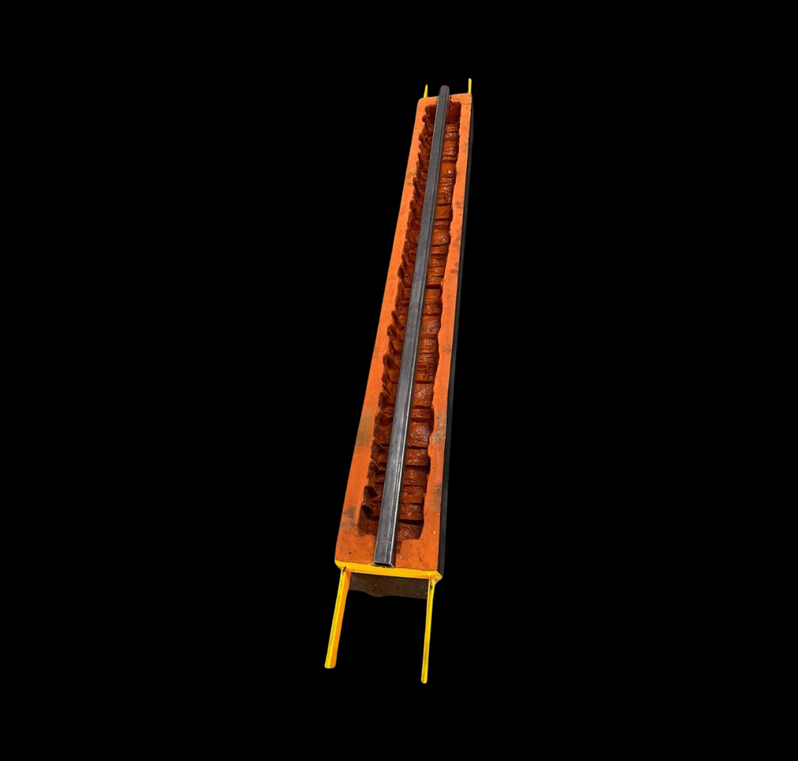
Draft is the taper on any face that has to slide past the mold during release. Insufficient draft causes the part to bind against the form as it lifts, and the consequences are predictable: chipped arrises, torn texture, surface pull-off where concrete stays on the mold face, and rising release-agent use. It also accelerates wear on the tool, because every cycle scrapes rather than releases.
The tradeoff is real. More draft means the part is no longer prismatic, and where both faces are visible or sections must stack, that taper has to be acceptable to the end user. Settle it on the drawing, not at the casting bed.
An undercut is worse than shallow draft, because it makes straight-line release geometrically impossible. Any recess, return or lip means the mold must either split so a section moves clear before the part lifts, or use a removable insert stripped separately. Both are solvable; both cost cycle time. If an undercut is decorative rather than functional, say so, because relaxing it is often cheaper than tooling around it.
One-piece or multi-part: how the parting line gets decided
A one-piece mold is faster to set and clean, with no joints to seal and no alignment to check each cycle. Where geometry allows it, it is almost always the right answer, and it is why self-contained mold systems demold quickly.
Once a part has undercuts, deep returns, or texture on more than one plane, the tool has to open, and the parting line has to go somewhere. On a visible face it leaves a witness mark crews grind off every part; on a hidden or chamfered edge it disappears. Tell the mold builder which faces are exposed in service, because working from geometry alone they have to guess.
Volume, cycle target and material choice
Expected volume is the number that most changes what the tool should be made from, and the one most often left out. Tooling is a cost-per-cast decision, not a purchase-price decision. A lighter or more easily modified form can be right for a short run; for sustained production the calculation inverts, and the durable option wins on cost per part even at a much higher purchase price.
Where a part needs maximum rigidity and long cast life, steel moulds for precast concrete are the usual answer. Where fine stone, brick or woodgrain texture straight off the mold face is the priority, a urethane face encased in a steel framework gives texture reproduction with dimensional stability; Elastoquip's mold systems are built that way. Cycle target belongs in the same conversation: a tool built around a two-day cycle and one built around several casts a day are different tools.
Custom precast molds and mold forms: how mould design runs
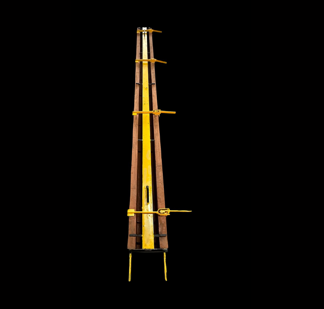
Custom precast molds, custom precast concrete mold forms and custom concrete casting tools are one product with three names. Each is a tool built for your part, not picked from a catalog. Precast concrete mould design follows the same steps each time.
- You send the drawings and the plant facts — everything on the checklist above, in one package.
- The builder checks the shape — for low draft, undercuts and deep returns that will make the part stick.
- The builder picks the layout — one piece or split, and where the parting line goes.
- Mix, placement and cycle time are agreed — and then the material: steel for rigidity, or a urethane face in a steel frame for texture.
- The quote comes last — once both sides are pricing the same tool.
When the new tool arrives, measure the first part off it against your drawing before production starts. Our guide to checking a precast mold supplier's track record shows how.
What goes wrong when a spec arrives incomplete
The recurring failures are not exotic. No draft is called out, the tool is built to the drawing, and the first parts bind on release. Embedment positions arrive after the design is fixed, and reinforcement clashes with a support the mold needs. Tolerances come as one blanket note, so either the tool is over-engineered against dimensions nobody checks, or the dimension governing fit-up was never held.
The fix is the same every time, and it is free: send the production context with the geometry. If you are unsure what is relevant, send more rather than less. Our FAQ covers common tooling questions, and drawings can be sent through contact us to start the review.
Frequently asked questions
Can I get custom precast concrete molds made from my own drawings?
Yes. Custom precast concrete mold tooling is normally built from the producer's own dimensioned drawings, supplied as 2D views or a 3D model. The mold manufacturer reviews the geometry, advises on mold configuration, concrete mix and cycle targets, and confirms the arrangement with you before fabrication begins.
What information does a mold manufacturer need from me?
At minimum: dimensioned drawings with tolerances marked as critical or nominal, draft angles allowed, the concrete mix and placement method, reinforcement and embedment details, target cycle time and production volume, required surface finish, and how the part will be demolded and handled. Curing method and any governing project specification should be included as well. Sending these together avoids a quote built on assumptions.
What happens if a part has too little draft angle?
Insufficient draft causes the part to bind against the mold face during release rather than sliding free. The visible results are chipped edges, torn texture and surface pull-off where concrete stays on the mold, along with rising release-agent use and faster wear on the tool itself. Adding draft on the drawing is far cheaper than compensating for it every cycle.
Does production volume change what the mold should be made of?
Yes, because tooling is a cost-per-cast decision rather than a purchase-price decision. Short runs can justify a lighter or more easily modified form, while sustained production favours durable construction such as steel moulds for precast concrete, which costs more upfront but far less per part. Stating expected casts per year and program life lets the mold builder recommend the right material.
When does a mold need to be multi-part instead of one piece?
A mold has to split when the part geometry prevents straight-line release, typically because of undercuts, deep returns, or texture required on more than one plane. One-piece molds are preferred where geometry allows, since they set faster, clean faster and have no joints to seal or align. If a mold must split, the parting line should sit on a hidden or chamfered edge so the witness mark does not have to be ground off every part.
Talk to our team
Send us your panel design, production volume and cycle targets and we will recommend a mold configuration and concrete mix to match. Or browse the full mold system range and fence designs.
Contact Elastoquip